
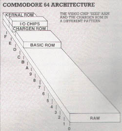
We're about to embark on a guided tour of the 6566 chip, which gives the Commodore 64 its video. It's called the VIC, for Video Interface Chip, that's the same name used for the 6560 used in the VIC computer, but the 6566 is a whole new story. Before setting off on our expedition, we need to establish a few landmarks which will place the chip within the Commodore 64 architecture.
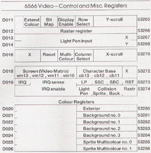
The 6566 chip related to memory in two ways. First, the chip's control registers are accessible in addresses 53248 to 53294 - or if you'd rather, hexadecimal D000 to D02E. We'll change these registers if we want to change the behaviour of the chip.
The chip itself looks directly into memory as it generates video. It is usually looking for at least 2 things: what characters to display, and how to display them.
It finds what characters to display in an area called "screen memory" or, more formally, the "video matrix". It finds out how to display the characters by looking at the "character generator" table, or the "character base".
Since the chip generates a lot of video, it looks at memory a great deal. Most of the time it can do this without interfering with the processor's use of memory; but every 500 microseconds or so, it needs to stop the processor briefly in order to get extra information.
This doesn't hurt anything: the pause is so short that we don't lose much processing time. But occasionally the microprocessor is engaged in timing a critical event, and does not want to be interrupted. In this case, it shuts off the 6566 chip until the delicate work is over. Ever wondered why the screen blanks when you read or write cassette tape? To give the computer an extra edge while timing tape, that's why.
When the video chip goes to memory for its information, it has a special problem: it can only reach 16K of memory. That's okay for most work.
For example, the screen (or video matrix) is usually located at 1024 to 3023 (hex 0400 to 07E7), so we'll use it there. But if we wanted to move screen memory to a new location, say 33792, we would need to work out some details since the chip would not normally be able to reach addresses so high in memory.
We are given some help in doing this by the 64 architecture itself. There are two control lines called VA15 and VA14 which allow us to select which block of 16K memory we want the video chip to use. Note that once we've selected a block, the chip must get all its information from that block; we can't mix and match.
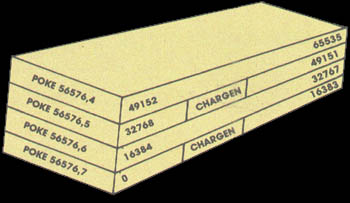
The control lines are available in address 56576 (hex DD00) as the two low order bits. The memory maps you get are:
POKE 56576,4 - the chip sees RAM from 49152 to 65535. There's no character generator; you'll have to make your own.
POKE 56576,5 - the chip sees RAM from 32768 to 36863, and from 40960 to 49151. The ROM character generator is in the slot from 36864 to 40959.
POKE 56576,6 - the chip sees RAM from 16384 to 32767. No character generator.
POKE 56576,7 - the chip sees RAM from 0 to 4095, and from 8192 to 16383. The ROM character generator is in the slot from 4096 to 8191. This is the normal Commodore 64 setup.
Note that the chip never has access to RAM at addresses 4096 to 8191 and 36864 to 40959. You will not be able to put screen memory or sprites there. Be careful with these. If you move the chip's memory area, you'd better be sure to move the screen. For example, try the following:
POKE 648,132: POKE 56576,5
You'll find yourself transferred to a new, alternate screen. The new screen will be "dirty" - it hasn't been cleaned up. Typing a screen clear will make things look neat and you may then play around with an apparently normal machine. When you've finished, turn the power off for a moment to restore your machine to the standard configuration.
Now for the 6566 chip itself. We'll go through the registers, but not in strict numerical order. Location 53265 (hex D011) is an important control location. It contains many functions; its normal value is 27 decimal. Values from 24 to 31 control the vertical positioning of the characters on screen. Try this:
FOR J=24 TO 31: POKE 53265,J: NEXT J
You'll see the screen move vertically, leaving an empty spot near the top. POKE 53265 back to 27. If we subtract 8 from the value in the 6566, the screen will lose a line: instead of 25 lines we'll have only 24. The best way to see this is to clear the screen; write TOP on the top line, BOTTOM on the bottom line (don't press RETURN!); then move the cursor to about the middle of the screen and type:
POKE 53265,19
You'll see the top and bottom trimmed to half a line each. Think about using these two features together. If we have a screen full of information, we would normally scroll when we wanted to write more - the characters would jump up a line. But if we can switch to 24 lines, slide the characters up gently, and then switch back to 25 lines, we'd have a smooth scroll.
If we subtract 16 from this location, we'll blank the screen. We mentioned this before: it will give the processor a little more accuracy in timing. In fact, this POKE is the key to allowing us to LOAD a program from the old style 1540 disk unit. If the disk hasn't been modified, it will deliver bits slightly too fast for the computer... but we can bridge the gap with POKE 53265,11: LOAD... and the loading will take place successfully. When the load is complete, we can get the screen back with POKE 53265,27.
The next control bit - value 32 - switches the display to pure bits. No more characters: the screen will be purely pixels as we switch to high resolution mode. We'll use a lot of memory for this one: memory to feed the screen will be 8,000 bytes.
High resolution needs to be carefully set up, but let's plunge right into it. Type POKE 53265,59 and you'll see an intricate pattern on the screen. What you are looking at now is a bit map of RAM memory addresses 0 to 4096, plus the character generator area.
The top of the screen will twinkle a little: those are the page zero values changing - things like the real time clock and interrupt values are constantly in motion.
In the bottom half of the screen, we'll see the character generator itself. Oddly enough, the characters are readable. That's because of the way high resolution bit mapping works: each sequence of eight consecutive bytes maps into a character space, not across the screen as you might think.
We're going to play around a little. First, clear the screen. Surprise! It doesn't clear, but the colours change. That's because screen memory, into which we are typing, holds colour information for the high resolution screen.
Now, we'll clean out a band of hi-res data by typing in a Basic line. We must do this blind: the screen won't help us. Type:
FOR J=3200 TO 3519: POKE J,0: NEXT J
If you've typed correctly, you'll see a blank band across the screen. Don't worry about the colour change as you type. Now we'll enter (blind again):
FOR J=3204 TO 3519 STEP 8: POKE J,255: NEXT J
That's all the high resolution fun we're going to have this session, but you may be starting to get an idea of what's going on. Turn off the power, and let's look at other things.
If we add 64 to the contents of 53265, we'll invoke the extended colour mode. This will allow us to choose both background and foreground colours for each character. Normally, we may only choose the foreground: the background stays the same throughout the screen. You lose some colours, but get better combinations.
Try POKE 53265,91. Nothing happens, except that the cursor disappears... or at least becomes less visible. Why? We've traded the screen reverse feature for a new background colour.
Try typing characters in reverse font, and see what happens. Try choosing some of the specialised colours - the ones you generate with the Commodore key rather than CTRL. See how you like the effect. Think how you might be able to use it.
Extended colour is purely a screen display phenomenon. POKE 53265,27 will bring all the characters you have typed back to their normal appearance.
There's one more bit in location 53265, the one we would get if we added 128. Don't do this now: this bit is part of a value we'll discuss later, the "raster value". You won't use this one out of Basic, but it can be handy at machine language speeds.
We've seen the variety of important controls that we can reach in location 53265 - vertical screen positioning, screen blank, bit mapping, extended colour. There's a second control location, at 53270 (hex D016); let's look at it.
The first thing we should note about this location is that the two high bits are not used. That means that we can usually poke only values 0 from 63 into there. It happens that if we PEEK 53270, we'll probably see a number that is 192 too big; if you want to see the working value, use PEEK (53270) and 63 which will throw away the unused part of the number.
We saw a vertical fine scroll in location 53265. Location 53270 has a horizontal fine scroll that works exactly the same way. Type:
FOR J=8 TO 15: POKE 53270,J: NEXT J
You'll see the screen characters slide over horizontally. As with the vertical fine scroll, we also have facilities for trimming the size of the screen.
Restore the screen to its original form with POKE 53270,8. Now, shrink the screen by typing POKE 53270,0... you'll see a character disappear from each end. In other words, you now have a 38 character screen instead of 40 characters. Don't forget that fine scroll and shrink can be effectively used together.
If you add 16 to the contents of 53270, you'll switch to multicolour mode. This is not the same as extended colour which we discussed previously; multicolour allows selected characters to be shown on the screen in a combination of colours. Extended colour, you may remember, allows screen background and foreground to be individually set on each character.
If you're familiar with the Vic20, you'll find that setting the multicolour mode makes the Commodore 64 behave in the same way. Here's the trick: we invoke multicolour on an individual character by giving that character a colour value greater than 7. This way the regular colours (red, blue, black) behave normally; but the new pastels (grey, puce) switch to multicolour mode.
You'll need to create a new character base to exploit the advantages of multicolour, since the old characters weren't drawn with colour in mind. We can however get a quick idea of the feature by invoking it. POKE 53270,24 sets up multicolour; the screen characters may turn a little muddy, but don't worry about them. Now set a primary colour such as cyan and type a line. Normal, right?
Next, set up one of the alternate colours (hold down the Commodore key and press a key from 1 to 8). Type some more; you'll get multicolour characters. They won't make much sense, since the character generator isn't building the colours suitably; but you can see that something new is going on.
Adding 32 to the contents of 53270 gives chip reset. You won't want to do this very often - it's done on your behalf when you turn the power on. If you do use it, remember that to make it work you must turn reset on and then off again. POKE 53270,32: POKE 53270,8 will clear you out of multicolour mode.
Location 53272 sets the location of screen RAM (the video matrix) and the character generator (the character base). Don't forget that they must be in the same 16K block as determined by the low bits of address 56576.
You can get the basic address of screen RAM as follows: take the contents of 53272 and divide by 16. Throw away the remainder and multiply by 1024; and you have the screen address.
You can get the basic address of the character base by dividing the contents of 53272 by 16. Take the remainder and multiply by 1024; that's the character base address. Both addresses will need to be adjusted to allow for the 16K quadrant we have selected.
Now, if we are in bitmap mode, we get the character base address in a slightly different way. Divide the contents of 53272 by 16; take the remainder and divide by 8, discarding the remainder; finally multiply by 8192. That's the bit image; it should be either 0 or 8192.
How does this work out in the standard Commodore 64? We may PEEK 53272 and see a value of 21. That means the screen is at INT (21/16) * 1024, or address 1024. Right on! The character matrix works out: the remainder of 21/16 is 5; drop one for the odd number, giving four; multiply by 1024 to get address 4096.
You may remember that our discussion last time indicated that locations 53267 and 53268 (hex D013 and D014) are the light pen registers. A light pen can be plugged into joystick port number 1; if it sees a suitable signal from the screen, the X and Y values will be latched into these registers. The light pen can be used on an interrupt basis; we can "stop the music" and get immediate action if we chose to set things up that way.
This is the second time we've mentioned interrupts. Perhaps we'd better discuss them a little more closely.
Interrupts are for machine language maniacs... things happen too fast for Basic to cope in this area. There are four types of interrupt: raster, light pen, and two kinds of sprite collision. We may even use all of them or none - and even when these signals are not used for interrupt, we can check them.
Location 53273 (hex D019) tells us which of the four events have occurred. We don't need to make the interrupts "live"; they will signal us any time the particular event happens. The weights are as follows:
1 (bit 0) - the raster has matched the preset line value
2 (bit 1) - a sprite has collided with the screen background
4 (bit 2) - a sprite has collided with another sprite
8 (bit 3) - the light pen has sensed a signal
128 (bit 7) - one of the above has triggered a live interrupt
Once any of the above take place, the bit will remain stuck on until you turn it off. How do you turn it off? This may sound goofy but you turn an interrupt signal off by trying to turn it on. Hmmm... let me try that again.
Suppose that we have both a raster and a light pen signal; we'll see a value of 9 (8 + 1) in the interrupt register. Now, suppose further that we are ready to handle the light pen, so we want to turn its signal off. We do this by storing 8 in the location 53273.
Huh? Wouldn't that turn it on? Nope; it turns off, and leaves the other bit alone. So after storing 8, we look at the register again and (you guessed it) we see a value of 1 there. Honest.
Location 53274 (hex D01A) is the interrupt enable register; it sees the above signals for "live interrupt". Select bits 0 to 3 corresponding to the interrupts you want. Whatever you select will now trigger a processor interrupt when it happens, and also light up that high bit of 53273.
Don't forget to shut the interrupt flag off when you service it, using the method indicated in the previous paragraph. Otherwise when you finish the job and return from the interrupt (with RTI) it will re-interrupt you all over again.
Some of the colours we have mentioned and some we have yet to discuss are neatly stored in addresses 53280 to 53286 (hex D020 to D026). We may store only values 0 to 15 here, for the sixteen Commodore 64 colours.
The chart shows it all; the exterior (border) colour, then four background colours (they may be selected as part of multicolour characters or bits); and finally, two colours reserved especially for sprites. RAM was replaced by the character generator ROM at this video chip address. And when we flipped to bit mapping in the last episode, we got a high resolution screen from address 0 (remainder still 5, divide by 8 giving 0, multiply by 8192 and still get 0).
If you'd like to try your hand at the arithmetic, flip to upper/lower case mode (hold down shift and press the Commodore key) and see what addresses have changed. Or if you'd rather, try typing in this and watch the action:
FOR J=1 TO 100: POKE 53272,21: POKE 53272,23: NEXT J
Location 53266 (hex D012) and the high bit of the previous location are not much use to the Basic programmer, but can be very valuable to the machine language tyro. Here's the idea: by looking at these locations, you can tell exactly where the screen is being scanned at that moment.
This allows you to change the screen as it's being scanned. Halfway down you could switch from characters to bitmap, or change to multicolour, or move a sprite that has already been displayed.
If you're really hot on machine language you may want to take an extra step. Instead of watching where the screen is, you can leave a message: "wake me when you get to scan line 100". Machine code tyros will recognise this as an interrupt request. How do you set the identity of the desired scan line? By placing it into the same locations, that's how. We have a dual function here. When we read, we recall the scan location; when we write, we store an interrupt value.
Earlier we discussed how the video chip gets its screen information directly from memory. We indicated that the chip must dig out all of its information from a single 16K slice. We might draw this as a diagram:
We can control which slice we want by manipulating the two low bits in address 56576 (hex DD00). Normally, the processor picks the slice from 0 to 16383.
Once we've picked a 16K block, we must get all screen data from this block - the "screen memory", the character set, and the sprites. We cannot get the screen data from one block, the character base from another, and sprites from still another. Because we are restricted, we must do a little planning and design our video information into our program.
After we have picked the 16K slice, we must set the video matrix (screen memory) to some point within it. We may pick any multiple of 1024 as a starting address. The normal 64 configuration is set to a value of 1, meaning we take the screen information from memory starting at address 1024. The video matrix, you may remember, is stored in the high nybble (that means multiply it by 16) of 53272 (hex D018).
We must pick our character base next. If we're in normal resolution, we may pick an even multiple of 1024 as a starting address: 0, 2084, 4096 etc. If we're in high resolution we must pick only values of zero and eight, meaning that the hi-res starting address will be either 0 or 8192.
The normal 64 configuration is set to 4 or 6 for either graphics or text mode, meaning we take our character set from 4096 or 6144. You probably remember that the character base is stored in the low nybble of 53272.
So we'd expect a normal 64 to place into address 53272 a video matrix of 1, times 16, plus a character base of 4 or 6, yielding a total of 20 or 22. (You may in fact see 21 or 23 if you PEEK the location, but the extra bit doesn't matter - it's not used.) And if we switch to high resolution without changing anything else, our character base of 4 or 6 will be trimmed back to zero... explaining why we saw zero page when we tried POKE 53265,48 earlier on in the discussion. Let's try a few specific design jobs.
We're quite satisfied with the screen and character set, but we'd like to add a few sprites to liven things up. Fine: the normal 64 configuration leaves room for about 4 sprites drawings (numbers 11, 13, 14 and 15) provided we don't need to use cassette tape during the program run. This may be enough for a lot of animation; all eight sprites could use a single drawing, if that suited the task.
If we needed more than four drawings, we might be tempted to move the start of Basic pointer to a higher location, making room for the extras. That can work quite well, but it will probably call for two programs: a configuring program and a final program... it's hard for a program to reconfigure itself and survive.
If we wish to use the regular character set as well as new ones that we might devise, we'll want to stay in the memory blocks from 0 to 16383 or 32768 to 49151 (these two blocks contain the ROM character generator at offset 4096 to 8191).
If we don't need regular characters at all - we intend to use our own - it may be more convenient to switch to either of the two other blocks: 16384 to 32767 or 49152 to 65535. Since there's nothing but RAM in these two, we may find some more room.
Note that some of these RAM addresses are "hidden" beneath ROMs - Basic from 40960 to 49151, and the Kernal from 57344 to 65535. The video chip sees only the RAM... but in a normally configured 64 system, programs will only see the ROM. You can POKE or store to the RAM beneath, but when you PEEK or load from these addresses you'll get the ROM.
That's okay; the video chip sees the RAM locations you have POKEd. Result: something for nothing! You can build a character base into RAM... and not lose any memory from your system.
This is a clear cut job. We want to move the screen to the same place that the Pet uses the screen. That's very straightforward from a video chip standpoint. (Note: if you type the following POKEs in one at a time, you may have to type blind for some of them.)
The Pet screen belongs at 32768, so we must select that slice with POKE 56576,5 so that we'll pick up RAM starting at 32768. The ROM character generator is still in place.
Since we want the screen (video matrix) to be positioned right at the start of the block, we must set it to a value of 0. The character base can stay at its value of 4 (for graphics mode), so we must set up address 53272 with zero times sixteen plus 4: POKE 53272,4
That completes the video, but we have a few other things to do to make Basic work in a sound manner. We must tell Basic where the new screen is located: POKE 648,128
And finally, we should set the start and end of Basic to correspond with a 32K Pet:
POKE 1024,0: POKE 44,4: POKE 56,128: NEW
Clear the screen and the job's done. Zero page usage is still different, so not all PEEKs and POKEs will automatically work on this reconfigured system... but Basic and screen now match the Pet.
There are only eight places in memory that we can place a high resolution screen: 0, 8192, 16384, 24576, 32768, 40960, 49152 and 57344.
We tend to chose the two 16K blocks that don't have the character generator, 16384 to 32767 and 49152 to 65535. That way, we'll have more clear RAM to use; there will be more space left for our video matrix and any sprites we need.
If we want to write characters on the hi-res screen, we'll have to generate them ourselves or steal them from the character generator. Here's an odd thing: the video chip sees the character ROM at two different addresses - but the processor chip (and that includes your program) sees the same 4K ROM only at a third location: 53248 to 57343. Most of the time the processor can't see the ROM anyway, since the addresses are overlaid with the I/O chips.
So if our program wants to see the character set, it must flip away the I/O chip with POKE 1,51 - stop, don't do it yet! There are two problems.
First, once the I/O chips are moved out - sound, video, interface, everything - you won't be able to type on the keyboard; so you'll never be able to type the POKE to put everything back!
Second, the interrupt program uses these I/O chips for quite a few things and it will go berserk the moment you take them out of action. So we must use a program or a multiple direct command to do the job; and we must temporarily lock out the interrupt activity. Type the following statements as a single line. These lock out the interrupt; flip out I/O; read part of the character; restore I/O; and restore the interrupt:
POKE 56333,127: POKE 1,51: X = PEEK (53256): POKE 1,55: POKE 56333,129
X will contain the top row of pixels for the letter "A". If you liked, you draw a character's shape with the following program:
100 INPUT"CHARACTER NUMBER:";A
110 IF A<0 OR A>255 THEN STOP
120 B=53248+8*A
130 C=56333
140 FOR J=0 TO 7
150 POKE C,127: POKE 1,51: X=PEEK(B+J)/128
160 POKE 1,55: POKE C,129
170 FOR K=1 TO 8
180 X%=X: X=(X-X%)*2
190 PRINT CHR$(32+X%*3);
200 NEXT K: PRINT
210 NEXT J
220 GOTO 100
To terminate this program, enter a number over 255. You'll note that most of the characters are drawn with "double width" lines. A video technician would tell you that this reduces the video frequencies and is likely to cause less picture smear.
| BACK | (c) 1983, Jim Butterfield |